
Hi Karl,
Sure, no problem.
Thanks,
Lorenzo
Hi Lorenzo,
Here is the reply that I got back from ACIS support.
We have checked the incident and the input files again and it looks the issue is because of the source STEP file itself. The STEP file shared by you have incorrect information about shell/voids in it, verified this by opening the file in CREO modeler and checking the error there.
Their solution was to separate one surface and restitch the model. This is essentially what the autoheal with rebuild option does.
Karl
Hi Karl,
Thank you for contacting me back. I don’t see any problem in my simple geometry and if that was the case it would mean that any geometries with such empty spaces inside would be incorrect.
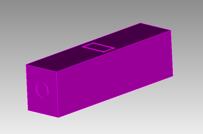
I made an even simpler case, attached here, and it’s the same thing.
Best Regards,
Lorenzo cilynder.step (6.0 KB)
Hi Lorenzo,
What CAD tool are you using to create the geometry? It isn’t clear to me from looking at the STEP file.
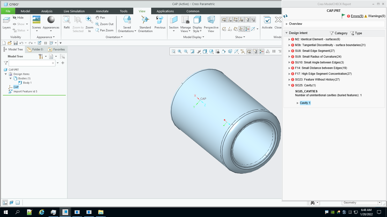
The image below was generated by ACIS support and shows the errors found when the cap.step part was loaded into Creo. I think the fundamental error is the last one showing the “unintentional cavities.”
Thanks,
Karl
Hi Karl,
I’m using OnShape as CAD tool and I don’t see any errors when importing the geometry. The second file I just sent you, is just a subtraction of two cylinders. So maybe an error when exporting step files in OnShape?
Thanks,
Lorenzo
Hi Lorenzo,
I’m thinking that there is an error with the OnShape STEP exporter for this case. Doing the autoheal with the rebuild option does fix it.
Karl
All,
I have a similar problem. I import a step file which represents the material (copper) associated with the boundary of a resonant electromagnetic cavity. I ultimately would like to mesh the volume bounded by the inner surface of the volume I import so that I can pass it to a electromagnetic eigen solver (omeaga3P).
I followed the steps presented in this thread but; see my journal file attached (along with the stp file) Nominally I would have expected the last step to produce two new volume: an external one between the outer surface of my imported volume and the bounding bring I added and the inner volume I am ultimately interested. Instead I get one volume. I suspect somehow cubi
processStpLinac3.jou (792 Bytes)
awa_linac_cleaned2.stp (3.7 MB)
t does not recognize what I imported as a “solid” volume. Thank you for any suggestion, – Philippe.
Hi Philippe,
I am testing our new release candidate and it seems to be producing the expected results. I’m not confident that the expected result is what you want though. It looks like there are paths from the interior to the exterior of the model. I made a couple of modifications to your model
brick x 10 y 12 z 40
tweak surface 1069 offset -0.5     # Ensure that the top is exterior

subtract vol 1 from vol 2 keep     # bug in keep_tool only. Keep both.
delete volume 2      # delete the extra exterior
I am fixing the keep_tool option for this release.
Is this what you are expecting?
To get what I think is really the exterior, I had to do some more work.
draw vol 3
separate surface 2085 2086 2087 2084
separate surface 2083 2082
delete body 4 to 6
separate surface 1092
delete body 3
delete body 8
draw body 7
At this point I can see an inlet that needs to be removed to create a closed volume for meshing.
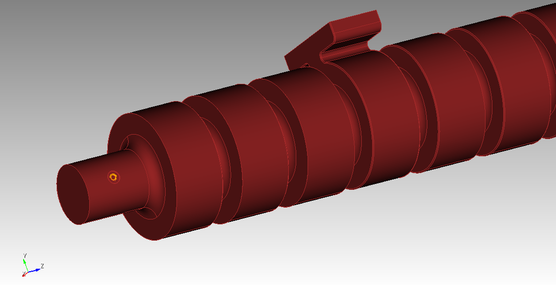
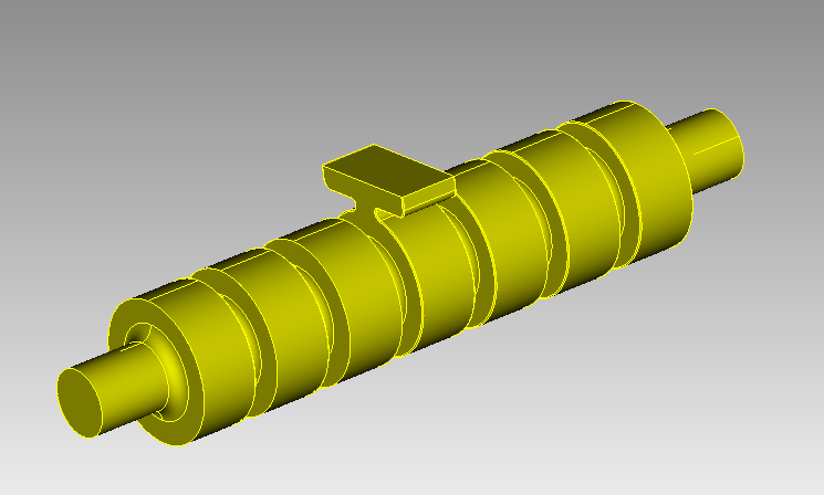
I removed the inlet and got a closed volume
separate surface 1095
separate surface 1086
delete body 9 to 11
tweak curve 2359 2358 2360 remove
Finally, I had to convince Cubit that this really was a closed volume. I did this by separating one surface out of the model and stitching the resulting bodies back together.
separate surface 2079
stitch body 7 12
compress
draw vol 2
Is this the model that you were expecting? (Otherwise, it was a good exercise in Cubit usage).
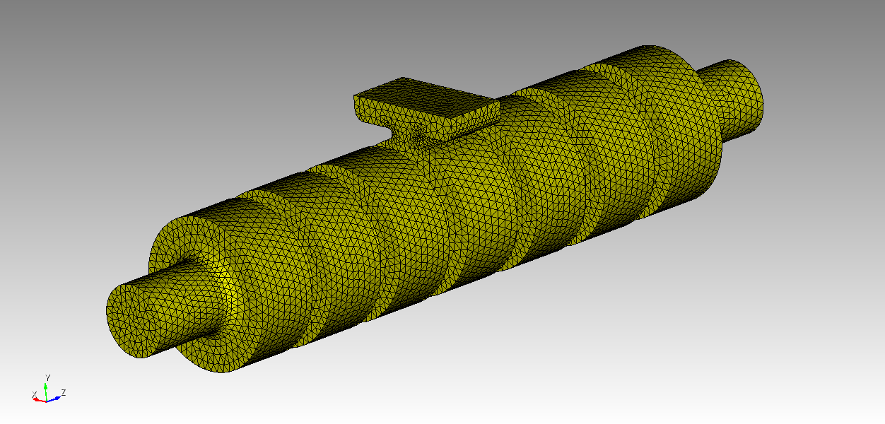
If you want a high-quality mesh on this model you will either need a very dense mesh, or you will have to remove a number of small blends and chamfers. The small surfaces will drive meshing time and number of elements up dramatically. You can reduce the meshing time by going to the Mesh/Surface/Mesh/Trimesh panel and toggling “Use Geometry Sizing” off.
I used the Geometry Powertool to find the small surfaces and I was able to find and remove all the small surfaces and then get a nice tet mesh on the model.
If you have questions on this last part, let me know and I will create a small video.
Thanks,
Karl
Hi Karl,
Thank you so much! Yes, the inlet you show is what I was trying to produce. I am not sure how to use the Geometry Powertool (I never used it) but let me give it a shot and get back to you if I have issues. Thank you! – Philippe.
Hi Phillipe,
Here is a video showing how to use the Geometry Powertool and some selection tools to speed up cleaning up your model. Loom | Free Screen & Video Recording Software. This is without editing and includes my mistakes. Forgive me for those. It should demonstrate the concepts!
This was done in our latest release candidate. There may be features in this release that are not in the current version of Coreform Cubit. The next release should be out by the beginning of next week at the latest. If you choose to, you can download release candidates from Coreform.com/Coreform Cubit/Downloads. Scroll down to “Latest Development Builds”
Karl