Hi Philippe,
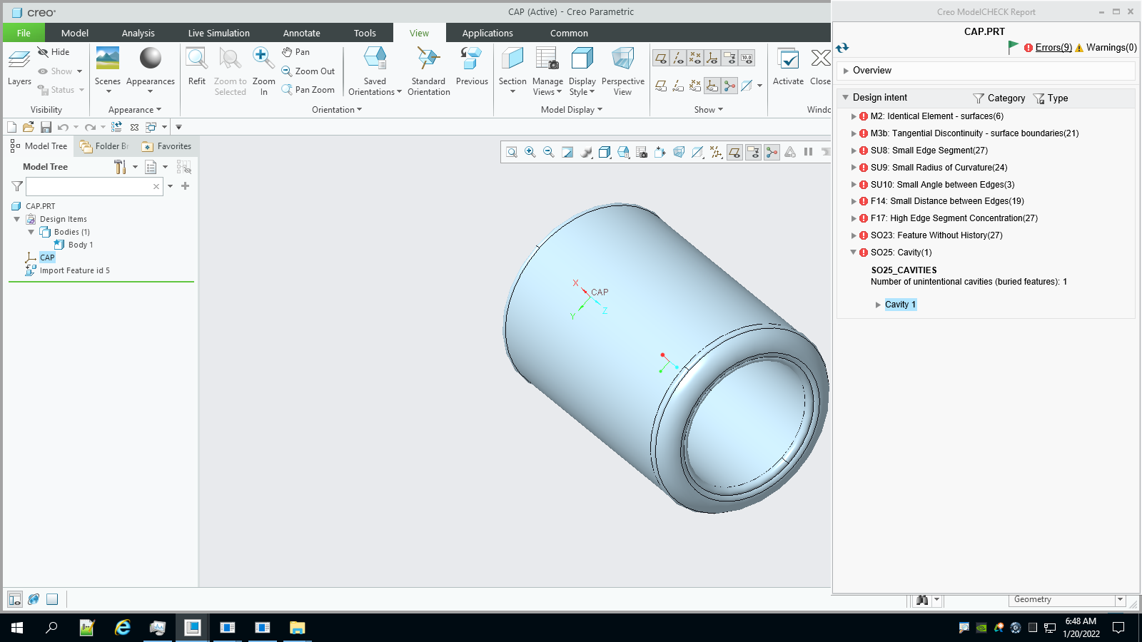
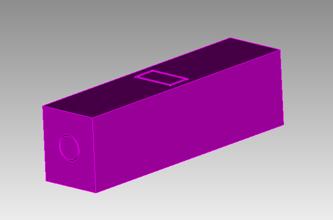
I am testing our new release candidate and it seems to be producing the expected results. I’m not confident that the expected result is what you want though. It looks like there are paths from the interior to the exterior of the model. I made a couple of modifications to your model
brick x 10 y 12 z 40
tweak surface 1069 offset -0.5     # Ensure that the top is exterior

subtract vol 1 from vol 2 keep     # bug in keep_tool only. Keep both.
delete volume 2      # delete the extra exterior
I am fixing the keep_tool option for this release.
Is this what you are expecting?
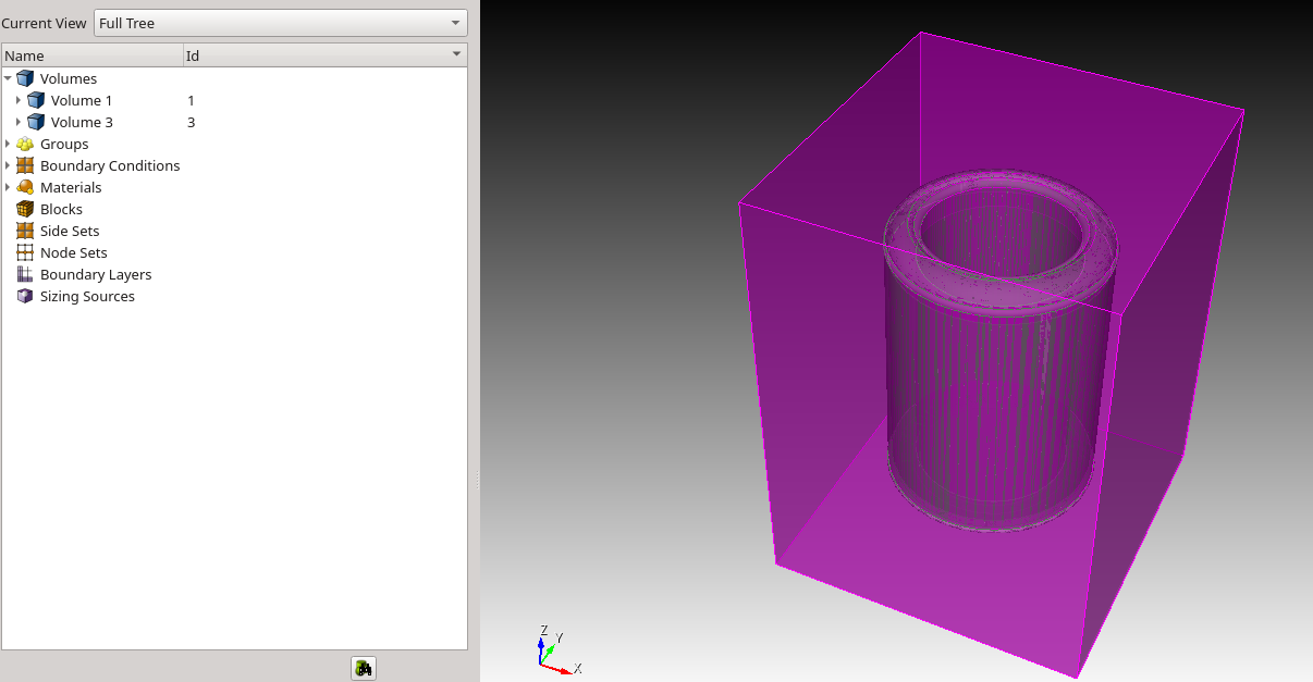
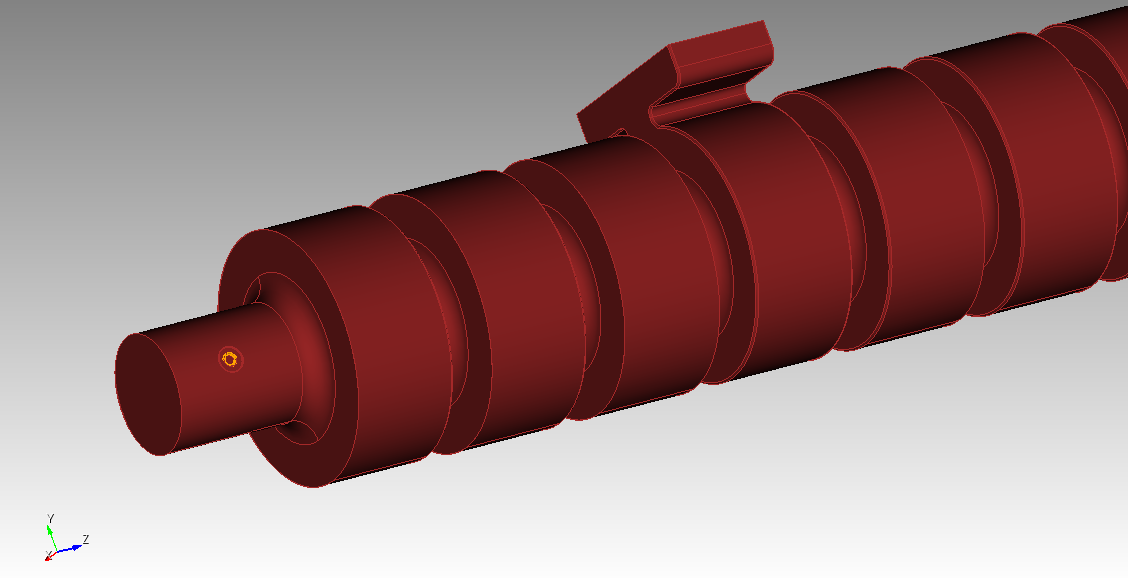
To get what I think is really the exterior, I had to do some more work.
draw vol 3
separate surface 2085 2086 2087 2084
separate surface 2083 2082
delete body 4 to 6
separate surface 1092
delete body 3
delete body 8
draw body 7
At this point I can see an inlet that needs to be removed to create a closed volume for meshing.
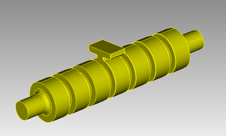
I removed the inlet and got a closed volume
separate surface 1095
separate surface 1086
delete body 9 to 11
tweak curve 2359 2358 2360 remove
Finally, I had to convince Cubit that this really was a closed volume. I did this by separating one surface out of the model and stitching the resulting bodies back together.
separate surface 2079
stitch body 7 12
compress
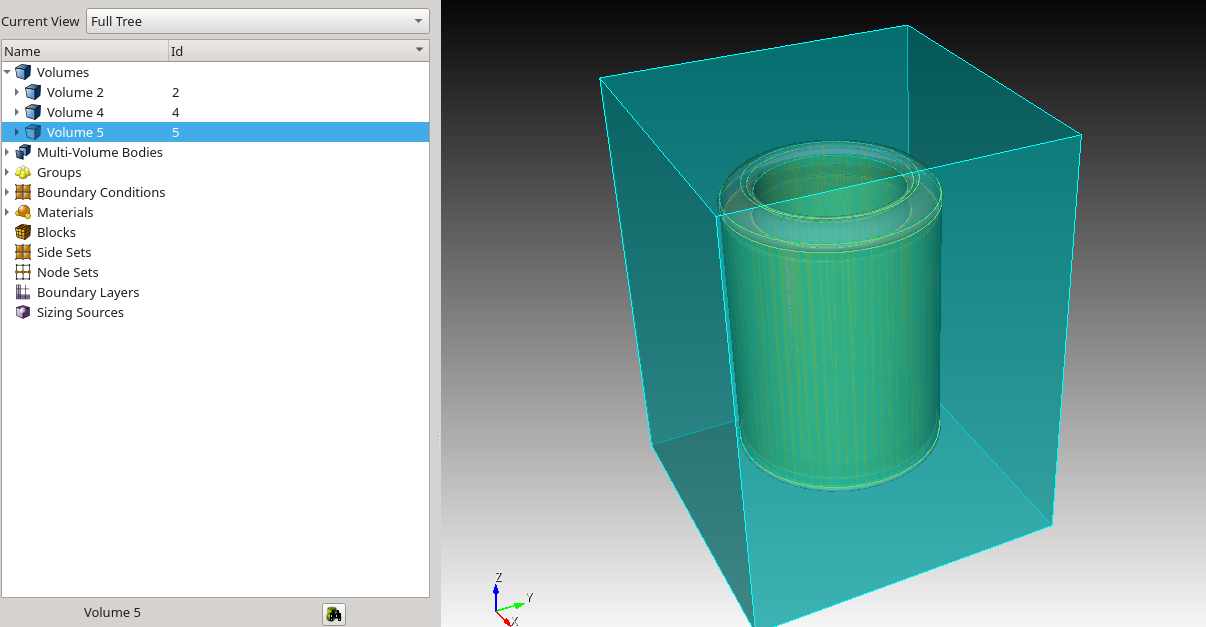
draw vol 2
Is this the model that you were expecting? (Otherwise, it was a good exercise in Cubit usage).
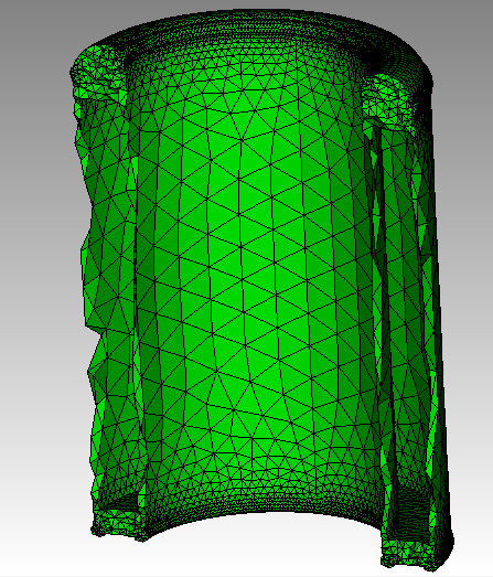
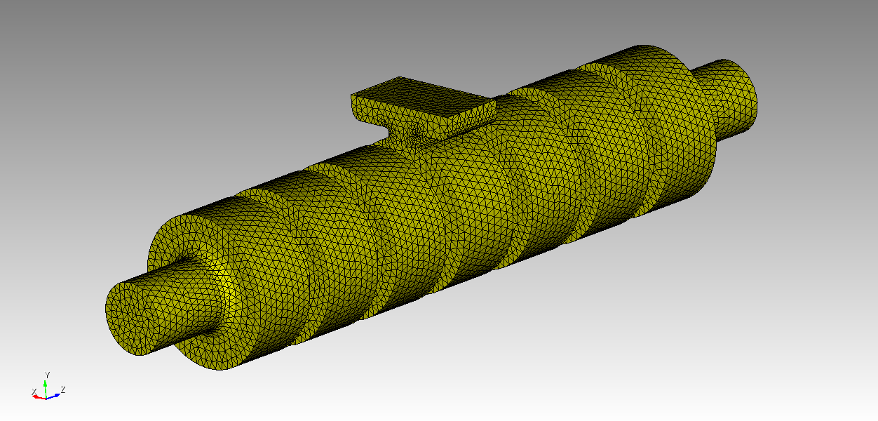
If you want a high-quality mesh on this model you will either need a very dense mesh, or you will have to remove a number of small blends and chamfers. The small surfaces will drive meshing time and number of elements up dramatically. You can reduce the meshing time by going to the Mesh/Surface/Mesh/Trimesh panel and toggling “Use Geometry Sizing” off.
I used the Geometry Powertool to find the small surfaces and I was able to find and remove all the small surfaces and then get a nice tet mesh on the model.
If you have questions on this last part, let me know and I will create a small video.
Thanks,
Karl